(Imported from old site; original post: Thursday, September 6, 2012)
It’s funny how an idea you just want to do for fun can evolve into something bigger than you thought, isn’t it? For now, and at least into the somewhat new future, what I am about to discuss will be referred to as my “NASA Project”. It sounds cool that way.
I have my senior design (part 1) project next semester, and I have been planning ahead for a long while now that I don’t want to do the traditional project of “Here. Analyze this bolt. Now print off graphs. Repeat. Try not to kill yourself from the monotony.” I decided that before my first semester here at UK even began! But it wasn’t until this past January or February that I really decided what I wanted to do: space. I wanted to do space. And I phrase it that way because it sounds better than “I want to accomplish a feat in the area of some of the most advanced subject matter in the history of man.”…well, okay, so it doesn’t sound better than that, but at least it’s shorter.
(Note: so I’m not doing this under my company, but dangit, it’s cool, and I’m still doing it, and so I’m gonna post about it!)
I brought this up at one point with my old fluids professor. He’s not old. The class was old. I mean it was taken in a semester prior. Anyway, he took an interest in the project (the specifics of which I will dive into here in a moment). Well, he informed me today, out of the blue, that he will be giving a talk at NASA Ames tomorrow morning, Friday, and he would like for me to prepare some slides about the project so he could discuss it and possibly drum up some support. I was thrilled, to say the least.
The project is about finding an economically-friendly way of testing thermal protection systems (TPS) for new spacecraft. I’m sure you’ve seen the black stuff on the bottom of the space shuttle. That is a type of TPS. Specifically, that TPS is an ablative TPS, which means that it would partially disintegrate during re-entry, helping carry heat away from the vehicle quicker than non-ablative TPS. But that’s not important, just interesting.
NASA has used roughly the same TPS for 50 years on the space shuttles (or rather had used; the space shuttle program has now been retired). Why is this? Legacy. Why fly a billion-dollar spacecraft with a TPS you don’t KNOW will work. You can test new TPS in an arc-jet on the ground all year long, but that doesn’t mean it’s proven itself in flight. I’d be a bit hesitant to put TPS on my extremely expensive spacecraft, too! Newer, better TPS exists already today, but nobody wants to be the first to “see if it really works”. This was all discussed by Ioana Cozmuta (NASA Ames) who conducted a seminar at UK, and this discussion was also the inspiration for this project.
So how do we get around this? By testing the TPS on a relatively inexpensive spacecraft, and form the TPS in a certain geometry where we can extrapolate how it will behave over a variety of different shapes and sizes. Now, forgive the lack of detail in the CAD drawings. I did this in 30 minutes:
I won’t go into too much detail, because many things will probably change after the project gets approved/started…at least it better be an approved project! How can you turn down space? Answer: you can’t.
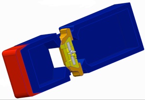
This is a 3U CubeSat, which means it is basically the size of 3 CubeSats stacked on top of each other. The red part of the picture is TPS that we already know works. The orange is the test-TPS to be evaluated. The yellow is the holders used to secure the TPS to the vehicle. The white is ultrasonic sensors. And the blue is obviously the body of the craft.
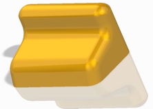
There can be a maximum of four (4) test-TPS (orange) on the vehicle, or maybe one can be a control-TPS, or maybe it’s all the same TPS but will all different geometries (and they can all be either ablative or non-ablative TPS, but they must ALL be of ONE of these; no mixing and matching of this detail). Many different possible combinations here. A possible geometry to be used is in Picture 3. It looks simplistic, but it is made in a way to test several different radii and slopes for the air to contact during re-entry. I’m almost positive this will have to be changed, because I came up with that in my head in literally 5-10 seconds, and I don’t have a PhD in fluid dynamics.
No matter the geometry, the test-TPS will be secured to the vehicle with the [yellow] holders. I could go into some overly complicated details about how it must secure properly at all points on the base of the test-TPS else it risks fragmentation and blah blah blah. It’s glue. It sticks. It holds. There is one thing of note about the holders: the surface has been coated with a non-ablative TPS. Why? In the event one of the TPS breaks off from the vehicle, the holder will then make contact with the air, having been shaped in a manner beforehand with the hope of stabilizing the craft during re-entry in the event something like this happens. It obviously needs some heat protection during this, so the non-ablative TPS performs this job.
The ultrasonic sensors are for continual mapping/monitoring of the surface of each test-TPS. This data will be constantly transmitted during re-entry, just in case the vehicle is lost for any reason. The data will also prove useful for observing the effects of re-entry at a specific time during re-entry. This time will correspond to a certain altitude, and knowing how things behave at a certain altitude is actually quite important for physicists. This, in turn, will allow for the validation of numerical models (computational fluid dynamics), and will allow engineers to develop even better TPS! This cycle will continue as more tests are performed with this craft.
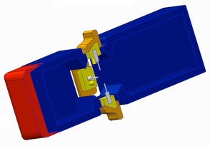
During launch and orbit, the vehicle will have the test-TPS tucked away to avoid damage from anything (e.g. debris), as shown in Picture 1. As soon as re-entry begins, the test-TPS is thrusted out to a stationary position via a worm-gear drive, the final position shown in Picture 2. The worm-gear is important, as it keeps the test-TPS at a synchronized distance from the vehicle, else the vehicle runs the risk of toppling–a low risk, but a risk nonetheless. Shortly thereafter, the backside of the craft will be severed, and a special radio cable (not pictured) will unravel itself from the inside of the vehicle, long enough to be sufficiently far enough away from the vehicle to not allow ion interference from the plasma generated due to re-entry.
Data is collected on the ground during flight (this is a LOT more complicated to do than you might think…or so I’ve been told). After a certain altitude is met, the radio cable is cut away from the vehicle, and a parachute (also not pictured) is deployed. At this time, the test-TPS is retracted back into the sides of the vehicle. The parachute should slow the craft down well enough that when it hits water (please please please hit water…70% chance!) the test-TPS is undamaged, and remains in the same state as it was before the parachute was deployed.
A flotation device of some sort, and a GPS will also be present on the craft, as well as various other instruments that measure whatever. Just if we have room/weight to spare, may as well use it. I really couldn’t care less what else is on it, as long as my mission is unhindered and successful.
After all, I just want to do space, remember?